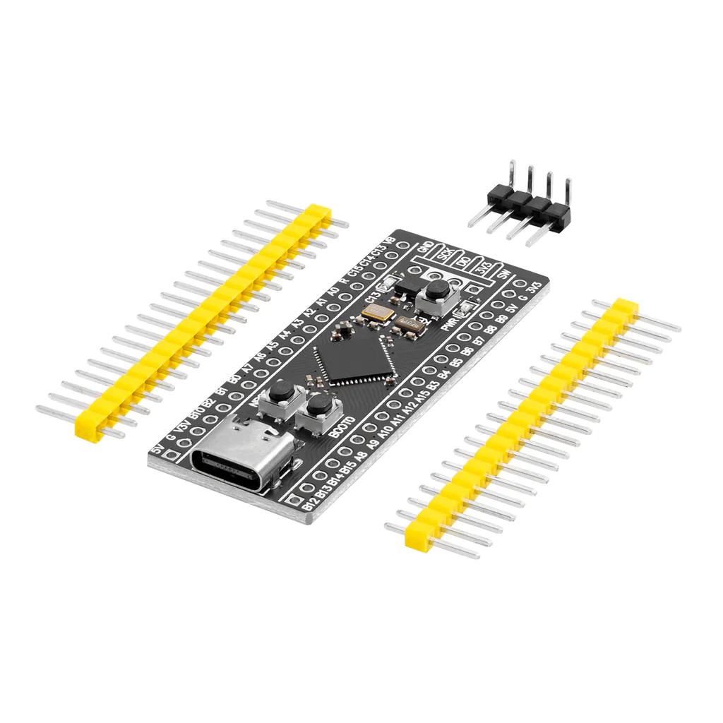


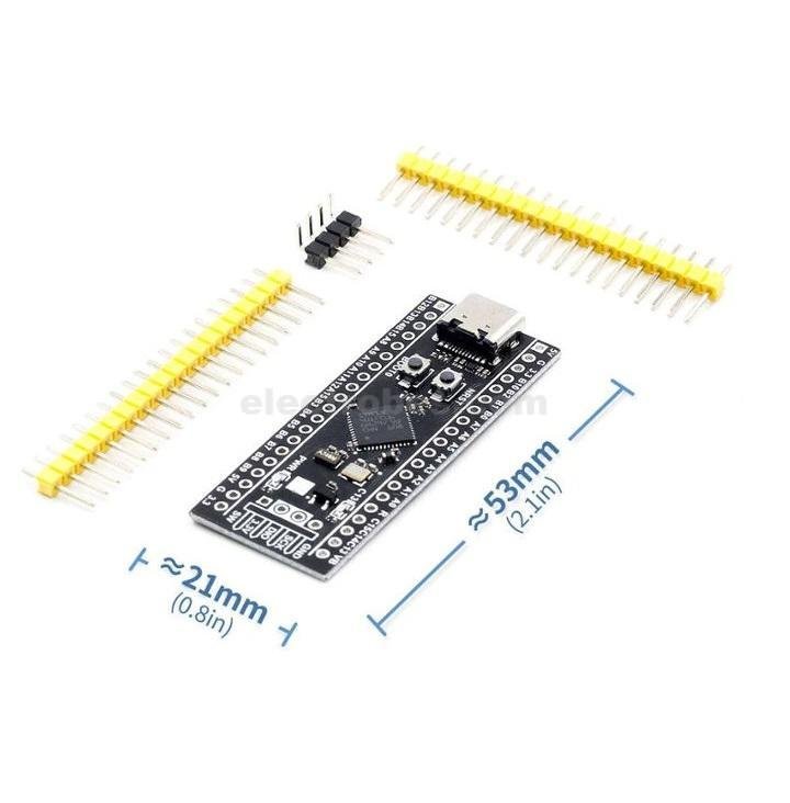


STM32F401 Minimum System Development Board Module STM32F401CCU6 STM32F4
In stock
₨ 950
In stock

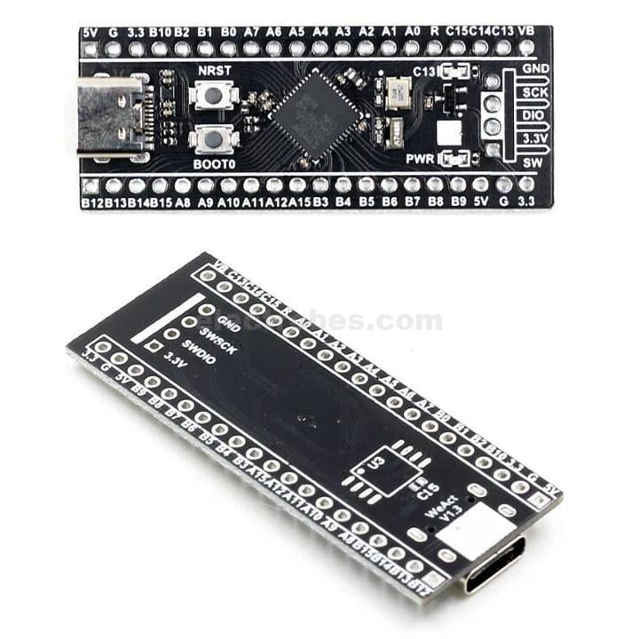
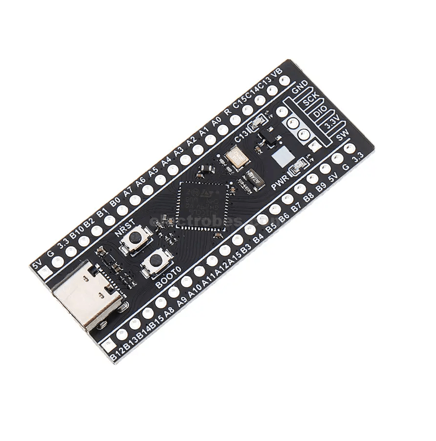
The STM32F401 ‘Black pill’ development board is an updated version of the original F103 based black pill. This newer version features a more powerful Core-M4F based ARM CPU which brings with it a number of enhanced features, including more flash, SRAM memory, a Floating Point Unit, and an increased number of peripherals, including built in USB type-C OTG support. However, possibly the most amazing feature of this development board is the price. When compared to Atmel based Arduino development boards this little development board boasts a very impressive array of features for a fraction of the cost.
Features:
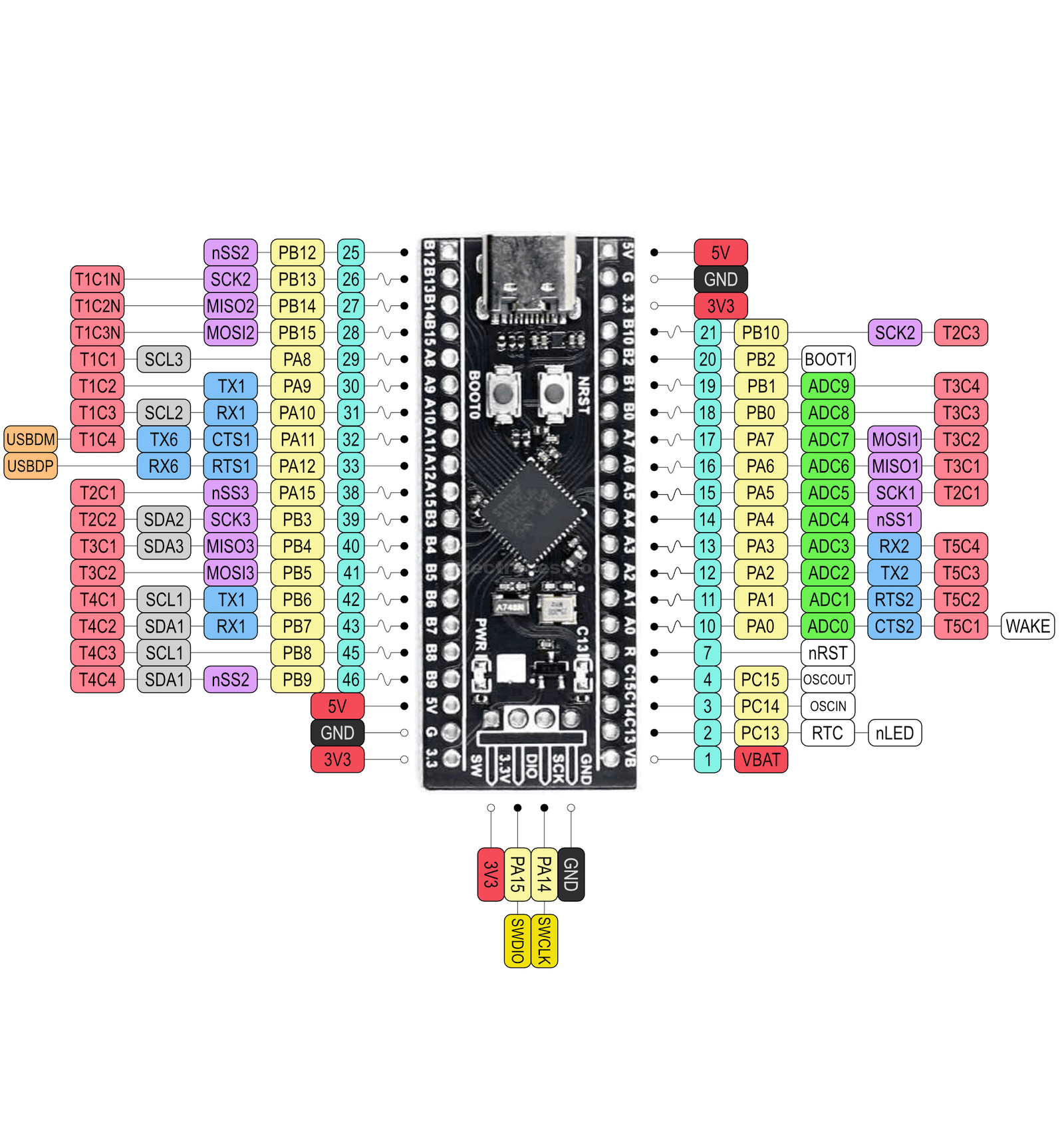
- STM32F411CEU6 (100Mhz) with 512KB FLASH & 128KB RAM
- Onboard LDO for 5V to 3.3V DC conversion
- 2x 20 Pin Single Line Header which gives access to all the IOs. The board comes with unsoldered header connectors.
- Header for SWD Programming Interface
- Switches for Reset, Boot Mode, User
- LED for Power and another connected on GPIO(C13)
- 25MHZ high speed crystal, 32.768Khz low speed crystal
- BOOT0 and NRST, releasing NRST to access serial port download, DFU download, using ST multi-in-one STM32 Cube Programmer burning software.
- Option to solder SPI Memory on the bottom side of the board.
- USB-C type Connector
Interface Description:
- SWD interface: support simulation, download and debugging
- Micro USB interface: power supply and USB communication, download is not supported
- USART1 interface: USART1 can be used to download programs, or use USART1 for communication
- MCU pin interface: lead out all I/O port pins for easy connection with peripherals
- 5V and 3.3V power input and output interface: often used for external power supply, or common grounding treatment with other modules
Other Equipment Description:
- Power indicator (PWR): The status of the power indicator, which can determine whether the power is stable
- User LED (PC13): Convenient for I/O output testing or indicating program operation
- Start to jump to select programming mode: (1, user flash memory 2, SRAM 3, system memory)
- Reset button: reset the chip for the user program
- 8M crystal oscillator: the frequency can be set to make the system main frequency 72MHz
- 32.768KHz crystal oscillator: can be used for built-in RTC or calibration
- Number of pins: 48
- Core: Cortex-M3
- Working frequency: 72MHz
- Storage resources: 64K Byte Flash, 20KByte SRAM
- Interface resources: 2x SPI, 3x USART, 2x I2C, 1x CAN, 37x I/O port
- Analog-to-digital conversion: 2x ADC (12 bits / 16 channels)
- Timer: 3 general timers and 1 advanced timer
- Debug download: support JTAG/SWD debug interface download, support IAP
- RT9193: 3.3V voltage regulator chip, maximum output 300mA
Related products
-
Gas Sensors, Modules and Breakout Boards, Sensors & Transducers
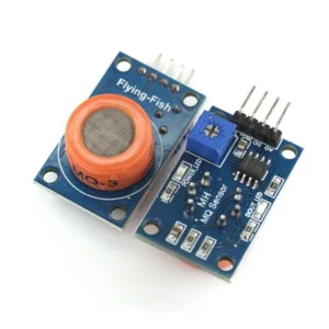
MQ-3 Alcohol Ethanol Gas Sensor Module
 Gas Sensors, Modules and Breakout Boards, Sensors & Transducers
MQ-3 Alcohol Ethanol Gas Sensor Module
- Sensor Type – Semiconductor
- Easy SIP header interface
- Compatible with most of the microcontrollers
- Low-power standby mode
- Requires heater voltage
- Good sensitivity to alcohol gas
- Fast response and High sensitivity
- Long life and low cost
- Requires simple Drive circuit
SKU: 0127 -
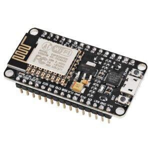
IOT Development Board, Modules and Breakout Boards
NodeMCU Amica V2 ESP8266 WiFi Module
- NodeMCU ESP8266 Wifi Development Board – Amica V2
- Breadboard Friendly
- The Development Kit based on ESP8266, integrates GPIO, PWM, IIC, 1-Wire and ADC all in one board.
- Power your development in the fastest way combining with NodeMCU Firmware!
- CP2102 based USB-TTL included, plug & play
- 10 GPIO, every GPIO can be PWM, I2C, 1-wire
- PCB antenna
SKU: 0109 -
Modules and Breakout Boards, Sensors & Transducers, General Sensors
5.8GHZ Microwave Radar Sensor Module XYC-WB-DC Smart Sensoring Switch 6-9M
-9%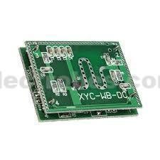 Modules and Breakout Boards, Sensors & Transducers, General Sensors
5.8GHZ Microwave Radar Sensor Module XYC-WB-DC Smart Sensoring Switch 6-9M
It uses Doppler radar technology, With the ability to automatically sensing to control another product, high sensitivity, sensor distance, reliability, wide-angle sensor, wide voltage range and other characteristics. Widely used in lighting conditions, anti-theft alarm is available online at electrobes-com-827299.hostingersite.com in Pakistan.
SKU: 0133 -
Modules and Breakout Boards, Compatibles for Arduino, Mainboards
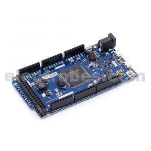
ARDUINO DUE AT91SAM3X8E ARM Cortex-M3 Board
-
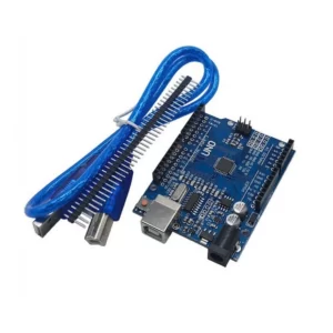
Compatibles for Arduino, Mainboards, Modules and Breakout Boards
Arduino UNO R3 SMD Variant With Cable
-34%