

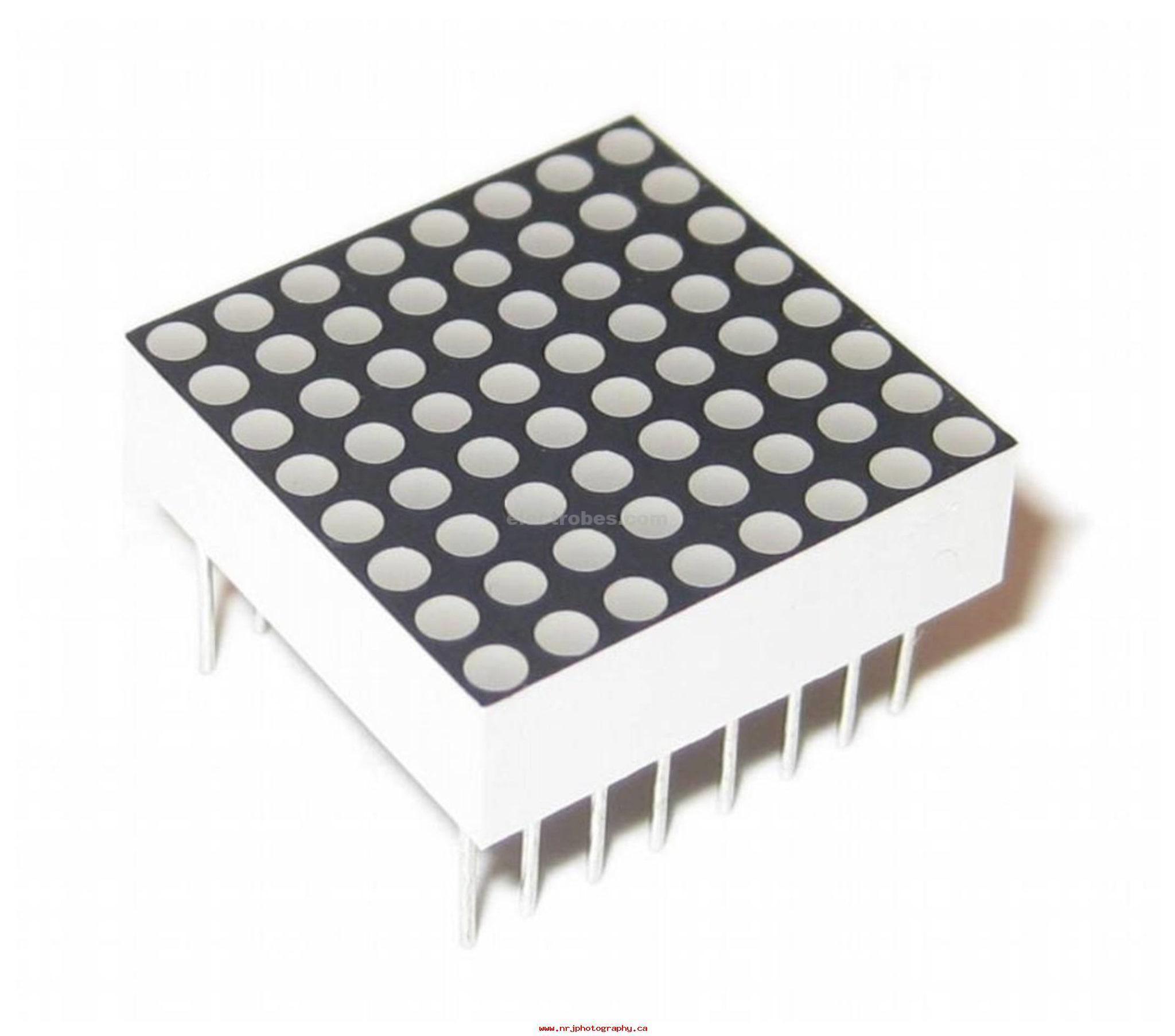
8X8 LED MATRIX Pin Configuration
LED MATRIX MODULES are available in different modules and each module will have different pin configuration. Here we have shown the pin configuration of 1388A LED matrix module. Different modules may have different pinout configuration but they have same functioning pins.
| Pin Number | Description |
| NEGATIVE TERMINALS | |
| 1 | PIN1 is taken out from 4th COLUMN |
| 2 | PIN2 is taken out from 2nd COLUMN |
| 5 | PIN5 is taken out from 1st COLUMN |
| 7 | PIN7 is taken out from 3rd COLUMN |
| 8 | PIN8 is taken out from 6th COLUMN |
| 9 | PIN9 is taken out from 8th COLUMN |
| 12 | PIN12 is taken out from 5th COLUMN |
| 14 | PIN14 is taken out from 7th COLUMN |
| POSITIVE TERMINALS | |
| 3 | PIN3 is taken out from 2nd ROW |
| 4 | PIN4 is taken out from 3rd ROW |
| 6 | PIN6 is taken out from 5th ROW |
| 10 | PIN10 is taken out from 4th ROW |
| 11 | PIN11 is taken out from 6th ROW |
| 13 | PIN13 is taken out from 1st ROW |
| 15 | PIN15 is taken out from 7th ROW |
| 16 | PIN16 is taken out from 8th ROW |
As given in above table any 8×8 LED MATRIX will have EIGHT POSITIVE TERMINALS and EIGHT NEGATIVE TERMINALS.
- EIGHT NEGATIVE TERMINALS are EIGHT COLUMNS.
- EIGHT POSITIVE TERMINALS are EIGHT ROWS.
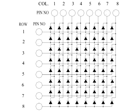
These 16 PINS are driven out from 64 LED SEGMENTS present in the MODULE. Those 64 SEGMENTS on the MODULE surface are the 64 LEDS arranged in MATRIX formation.
The internal structure of any LED MATRIX MODULE will be same and is shown below.
How to solve PIN CONFIGURATION issue
As shown above the POSITIVE and NEGITIVE PINS of MATRIX MODULE are irregular and may lead to problems while controlling the LEDs. This issue becomes even more complex when choosing a different MODULE. The best way to solve these problems is rearrange the terminals based on FUNCTION of PIN instead of PIN NUMBER. After rearranging the PINS we will have something as below.
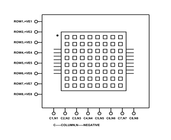
As shown in figure, by rearranging the EIGHT ROWS or POSITIVE and EIGHT COLUMNS or NEGATIVE we can completely eliminate the problem of PIN CONFIGURATION. As every module will have same ROWS and COLUMN even if MODULE outlets are random.
- Forward Voltage for EACH SEGMENT or LED turning ON: 1.5V-2.0V (2.0V being absolute maximum forward voltage)
- EACH SEGMENT or LED Forward Current during ON: 10mA – 15mA (Typically 10mA, 15mA being absolute maximum forward current)
- EACH SEGMENT or LED Reverse Voltage Maximum: 5V
- Maximum operating temperature: – 25°C to + 60°
Based on 1 review
Add a review
You must be logged in to post a review.
Related products
- Audio & Visual, General Sensors, Modules and Breakout Boards, Sensors & Transducers
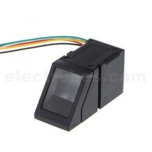
R307 Optical Fingerprint Scanner Module for Arduino
 Audio & Visual, General Sensors, Modules and Breakout Boards, Sensors & Transducers
R307 Optical Fingerprint Scanner Module for Arduino
- R307 is an optical fingerprint module integrates a fingerprint algorithm chip with functions such as fingerprint entry, image processing, feature extraction, template generation, template storage, fingerprint comparison (1: 1) and fingerprint search (1: N).
- The fingerprint reader can perform secondary development and be embedded in various end products, e.g. For example: access control, presence, safe, car door locks.
- Low power consumption, low cost, small size, excellent performance.
- Professional optical technology, precise module manufacturing technology.
SKU: 0737 - Audio & Visual, LCD & Display
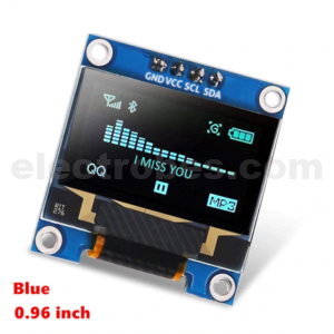
0.96 Inch 128×64 IIC I2C OLED Blue Display Module For Arduino
This OLED display module is small, only 0.96″ inch diagonal, it is made of 128×64 individual blue OLED pixels, each one is turn on or off by the controller chip. It has white backlight and can work without backlight, OLED display is higher compared to that of LCD display, you will like the miniature for its crispness. This module uses I2C to communicate with microcontroller such as Arduino.
SKU: 0537

zero (verified owner) –
I received them in Orange colored LEDs and they are really good, I strongly recommend these! I am completely satisfied with my purchase!
zero –