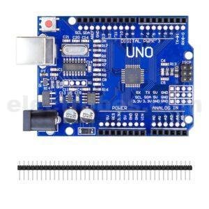
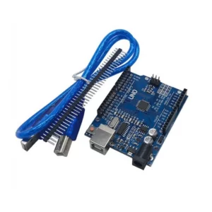
Arduino Nano V3 Pre-Soldered Pins with USB Cable
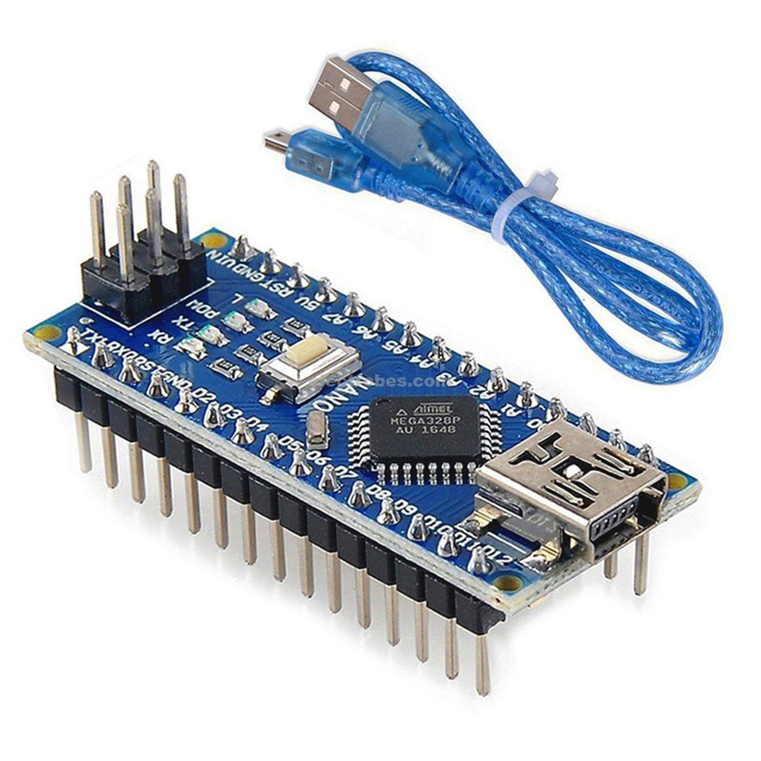
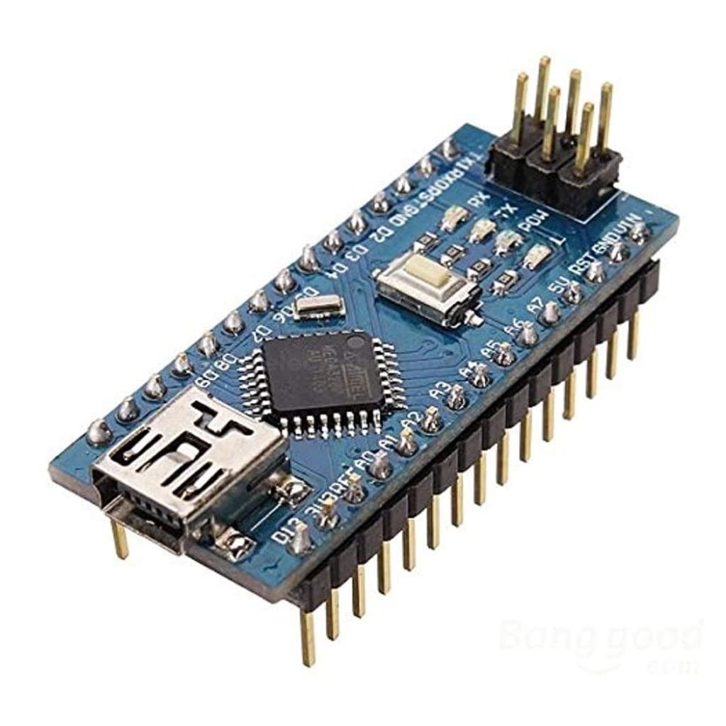
The Arduino Nano v3 available at electrobes in pakistan is a small, complete, and breadboard-friendly board based on the ATmega328P (Arduino Nano 3.0). It has more or less the same functionality of the Arduino Duemilanove, but in a different package. It lacks only a DC power jack, and works with a Mini-B USB cable instead of a standard one.
In stock
₨ 900
In stock
Arduino Nano V3 Pre-Soldered Pins with USB Programming Cable
The Arduino Nano is a small, complete, and breadboard-friendly board based on the ATmega328P (Arduino Nano 3.x). It has more or less the same functionality of the Arduino Duemilanove, but in a different package. It lacks only a DC power jack, and works with a Mini-B USB cable instead of a standard one.
Memory
The ATmega328 has 32 KB, (also with 2 KB used for the bootloader. The ATmega328 has 2 KB of SRAM and 1 KB of EEPROM.
Input and Output:
Each of the 14 digital pins on the Nano can be used as an input or output, using pinMode(), digitalWrite(), and digitalRead() functions. They operate at 5 volts. Each pin can provide or receive a maximum of 40 mA and has an internal pull-up resistor (disconnected by default) of 20-50k Ohms. In addition, some pins have specialized functions:
- Serial: 0 (RX) and 1 (TX). Used to receive (RX) and transmit (TX) TTL serial data. These pins are connected to the corresponding pins of the FTDI USB-to-TTL Serial chip.
- External Interrupts: 2 and 3. These pins can be configured to trigger an interrupt on a low value, a rising or falling edge, or a change in value. See the attachInterrupt() function for details.
- PWM: 3, 5, 6, 9, 10, and 11. Provide 8-bit PWM output with the analogWrite() function.
- SPI: 10 (SS), 11 (MOSI), 12 (MISO), 13 (SCK). These pins support SPI communication, which, although provided by the underlying hardware, is not currently included in the Arduino language.
- LED: 13. There is a built-in LED connected to digital pin 13. When the pin is HIGH value, the LED is on, when the pin is LOW, it’s off.
The Nano has 8 analog inputs, each of which provide 10 bits of resolution (i.e. 1024 different values). By default they measure from ground to 5 volts, though is it possible to change the upper end of their range using the analogReference() function. Analog pins 6 and 7 cannot be used as digital pins. Additionally, some pins have specialized functionality:
- I2C: A4 (SDA) and A5 (SCL). Support I2C (TWI) communication using the Wire library (documentation on the Wiring website).
There are a couple of other pins on the board:
- AREF. Reference voltage for the analog inputs. Used with analogReference().
- Reset. Bring this line LOW to reset the microcontroller. Typically used to add a reset button to shields which block the one on the board.
Package Includes:
- 1 x Arduino Nano Pre-soldered Pins
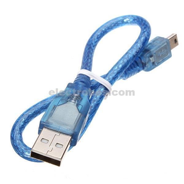
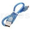
- 1 x Connecting USB 2.0 Cable


| Microcontroller | ATmega328P – 8 bit AVR family microcontroller |
| Operating Voltage | 5V |
| Recommended Input Voltage for Vin pin | 7-12V |
| Analog Input Pins | 6 (A0 – A5) |
| Digital I/O Pins | 14 (Out of which 6 provide PWM output) |
| DC Current on I/O Pins | 40 mA |
| DC Current on 3.3V Pin | 50 mA |
| Flash Memory | 32 KB (2 KB is used for Bootloader) |
| SRAM | 2 KB |
| EEPROM | 1 KB |
| Frequency (Clock Speed) | 16 MHz |
| Communication | IIC, SPI, USART |
Based on 1 review
Add a review
You must be logged in to post a review.


Asad Asif (verified owner) –
they are good quality controllers, seller send all the items on time.
highly recommend this seller
Asad Asif –