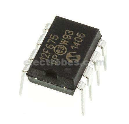
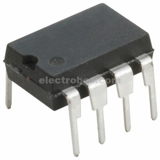
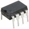
PIC12F675 – I/P 8-PIN PIC MCU Microcontroller
| CPU | 8-bit |
| Total number of pins | 8 |
| Programmable pins | 6 |
| Communication Interface | ICSP or In-Circuit Serial Programming Interface (13,14 Pins) [Can be used for programming this controller] |
| ADC Feature | 4 channels of 10-bit resolution |
| Timer Feature | One 8-bit counter, One 16-bit counter |
| PWM channels | Not available |
| Analog Comparator | Available-1 |
| External Oscillator | Up to 20MHz |
| Internal Oscillator | 4MHz Internal R-C Oscillator factory calibrated to ±1% |
| Program memory / Flash memory | 2Kbytes[100000 write/erase cycles] |
| CPU Speed | 1MIPS @ 1MHz |
| RAM | 64bytes |
| EEPROM | 128bytes |
| Watchdog Timer
|
Available and is featured with Independent
Oscillator for Reliable Operation |
| Power Save Modes | Available |
| Operating Voltage | 2.0V to 5.5V |
| Maximum current to any I/O pin | IN :25mA
OUT : 25mA |
| Operating Temperature | -40°C to +125°C |
| Maximum current into VDD pin | 250mA |
| ADCs | 4 x 10 bit |
| ADC Resolution | 10bit |
| RAM Size | 64 B |
| Maximum Frequency | 20MHz |
Out of stock
₨ 200
Out of stock
PIC12F629/675 8-Bit Flash Microcontrollers
Microchip’s PIC12 Microcontrollers (MCUs) were the world’s first 8-Pin microcontrollers. Originally launched as One Time Programmable (OTP) parts, this range of devices continues to expand as extra features and further improvements are added.
The PIC12F629/675 family of microcontrollers is based upon Microchip’s mid-range core with an 8 level deep hardware stack and 35 instructions. These MCUs provide up to 5 MIPS, 1.75 Kbytes program memory with data memory consisting of 64 bytes RAM and 128 bytes EEPROM. On board is a RC oscillator with ±1% accuracy.
Features
35 Instructions
8 Level Hardware Stack
4 MHz Internal Oscillator
6 I/O Pins
1 Comparator
4 Channel 10-bit Analogue to Digital Converter (ADC) – PIC12F675 only
One 8-bit Timer
One 16-bit Timer
In Circuit Serial Programming (ICSP)
Microchip PIC12F 8-bit PIC® Microcontrollers
Microchip’s PIC12F Microcontrollers (MCUs) were the world’s first 8-Pin microcontrollers. Originally launched as One Time Programmable (OTP) parts, this range of devices continues to expand as Microchip adds extra features, further improves specifications and continues to offer ever greater value. Key to the success of the PIC12F was the internal RC oscillator that allowed six I/O channels in an 8-pin package. Later versions of this RC oscillator are configurable between 31kHz and 32MHz.
Pin configuration:
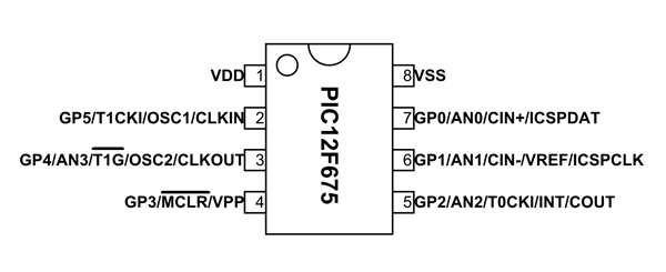
PIC12F675 is an 8 pin device and many of the pins can perform multiple functions as shown in above PIC12F675 pin diagram. The description for each of these functions is given below.
| Pin | Function | Description |
| 1 | VDD | Positive Power Supply |
| 2 | GP5/T1CKI/OSC1/CLKIN | GP5: General purpose I/O pin 5
T1CKI: Timer1 external clock input OSC1:Oscillator pin 1 CLKI: External clock source input |
| 3 | GP4/ AN3/ T1G/OSC2/CLKOUT | GP4: General purpose I/O pin 4
AN3: Analog input 3 T1G: Timer1 gate OSC2: Oscillator pin 2 CLKO: Clock source output |
| 4 | GP3/MCLR/VPP | GP3: General purpose I/O pin 3
MCLR: Master Clear Input or Reset pin VPP: Programming voltage |
| 5 | GP2/AN2 /T0CKI/INT/COUT | GP2: General purpose I/O pin 2
AN2: Analog input2 T0CKI: Timer0 clock input INT: External Interrupt COUT: Comparator output |
| 6 | GP1/AN1/CIN-/VREF/ICSPCLK | GP1: General purpose I/O pin 1
AN1: Analog input1 CIN-: Comparator input VREF: External Voltage reference ICSPCLK: Serial Programming Clock |
| 7 | GP0/AN0/CIN+/ICSPDAT | GP: General purpose I/O pin
AN0: Analog input0 CIN+: Comparator input ICSPDAT: Serial Programming Data I/O |
| 8 | VSS | Ground |
Based on 1 review
Add a review
You must be logged in to post a review.




ammar173 (verified owner) –
Working like a charm. Thanks for quality product.
ammar173 –